
Hydraulic symbols are the hidden language behind powerful machines that shape our modern world. From construction excavators digging deep foundations to aircraft landing gear systems, these symbols quietly control how fluid power moves, reacts, and performs.
When you first look at a hydraulic diagram, it can feel confusing and even overwhelming. But once you understand hydraulic symbols, everything starts to make sense like a map that suddenly becomes readable. You begin to see how pressure flows, how valves respond, and how energy is controlled with precision.
This guide will help you understand hydraulic symbols in a simple, human friendly way. You will not only learn what they mean, but also why they exist, how engineers use them, and what emotional logic they carry in design thinking. By the end, you will read hydraulic schematics like a trained technician.
Let’s break this complex language into something clear, practical, and surprisingly interesting.
Hydraulic Symbols PDF
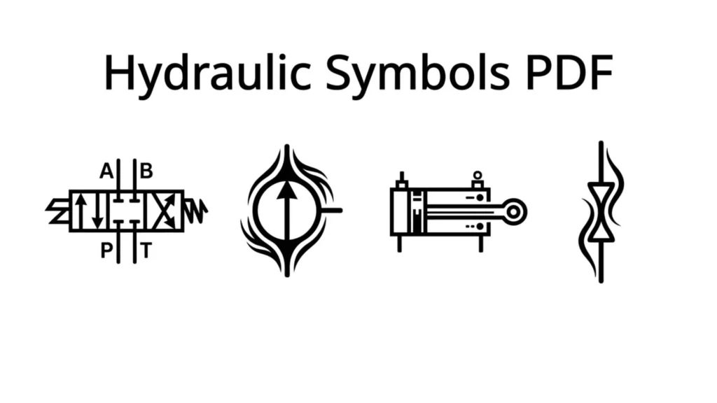
A hydraulic symbols PDF is a valuable reference guide for engineers, technicians, students, and maintenance professionals. It contains standardized hydraulic circuit symbols used in schematics, diagrams, and technical drawings.
These PDFs help users identify pumps, valves, cylinders, motors, filters, reservoirs, and flow control devices. Having a hydraulic symbols guide makes it easier to read hydraulic circuit diagrams and troubleshoot hydraulic systems.
Hydraulic Symbols PDF Download
Many professionals search for hydraulic symbols PDF downloads to learn hydraulic schematics and system design. A quality PDF typically includes:
- Hydraulic valve symbols
- Pump symbols
- Hydraulic cylinder symbols
- Flow control symbols
- Pressure control symbols
- Hydraulic motor symbols
- Reservoir symbols
These resources are commonly used in mechanical engineering, industrial maintenance, fluid power training, and technical education.
Mechanical Hydraulic Symbols PDF
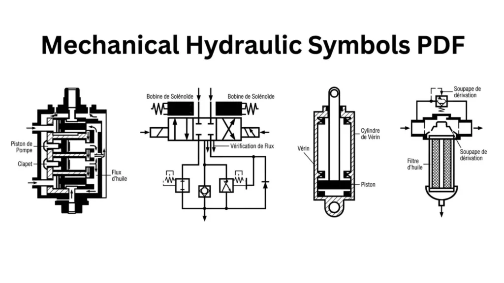
Mechanical hydraulic symbols are standardized graphical representations used in hydraulic engineering. They allow engineers and technicians to communicate system designs without using lengthy descriptions.
Common mechanical hydraulic symbols include:
- Hydraulic Pumps
- Hydraulic Motors
- Directional Control Valves
- Pressure Relief Valves
- Check Valves
- Cylinders
- Filters
- Accumulators
Understanding these symbols is essential for reading hydraulic blueprints and equipment manuals.
Hydraulic Valve Symbols
Hydraulic valve symbols represent devices that control the direction, pressure, and flow of hydraulic fluid.
Common hydraulic valve symbols include:
| Valve Type | Function |
|---|---|
| Directional Control Valve | Controls fluid direction |
| Pressure Relief Valve | Limits system pressure |
| Check Valve | Allows one-way flow |
| Flow Control Valve | Regulates flow rate |
| Pressure Reducing Valve | Lowers downstream pressure |
| Sequence Valve | Controls operation order |
These symbols appear in hydraulic circuit diagrams used across manufacturing, construction, and industrial systems.
Rexroth Hydraulic Symbols PDF
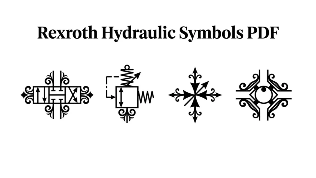
Bosch Rexroth hydraulic symbols PDFs are widely used in industrial automation and fluid power systems. Rexroth follows international standards for hydraulic schematic symbols, making their documentation useful for engineers worldwide.
A Rexroth hydraulic symbols guide often includes:
- ISO hydraulic symbols
- Directional valve symbols
- Hydraulic pump diagrams
- Pressure control devices
- Hydraulic actuator symbols
- Circuit design examples
These references help users understand and design professional hydraulic systems.
Hydraulic Symbols and Meanings
Hydraulic symbols use simple shapes and lines to represent system components and functions.
Common hydraulic symbols and meanings include:
| Symbol Type | Meaning |
|---|---|
| Pump | Creates fluid flow |
| Motor | Converts fluid power to motion |
| Cylinder | Produces linear movement |
| Valve | Controls fluid direction or pressure |
| Filter | Removes contaminants |
| Reservoir | Stores hydraulic fluid |
| Accumulator | Stores hydraulic energy |
Understanding hydraulic symbols and meanings helps technicians diagnose problems and maintain equipment efficiently.
Rexroth Hydraulic Symbols PDF Free Download
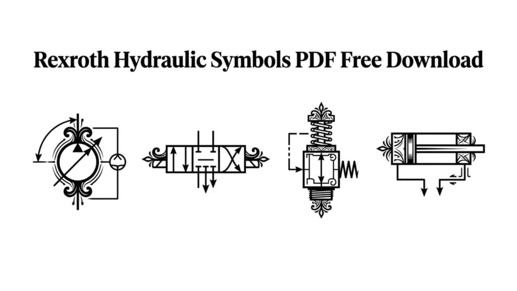
Many engineers and students look for Rexroth hydraulic symbols PDF free download resources to study hydraulic system design. These documents often contain comprehensive symbol libraries based on ISO standards used throughout the fluid power industry.
Typical topics include:
- Hydraulic circuit symbols
- Valve identification charts
- Actuator symbols
- Hydraulic power units
- Flow and pressure control diagrams
- System troubleshooting references
These materials are useful for training, maintenance, and engineering applications.
Hydraulic Symbols Chart
A hydraulic symbols chart provides a quick overview of the most commonly used hydraulic components and their schematic representations.
| Component | Purpose |
|---|---|
| Pump | Generates hydraulic flow |
| Motor | Produces rotational movement |
| Cylinder | Creates linear force |
| Check Valve | Prevents reverse flow |
| Relief Valve | Protects against overpressure |
| Filter | Cleans hydraulic fluid |
| Reservoir | Stores fluid |
| Accumulator | Stores energy |
A hydraulic symbols chart is commonly displayed in workshops, engineering offices, training centers, and maintenance departments to simplify hydraulic circuit interpretation.
What Are Hydraulic Symbols and Why They Matter in Fluid Power Systems
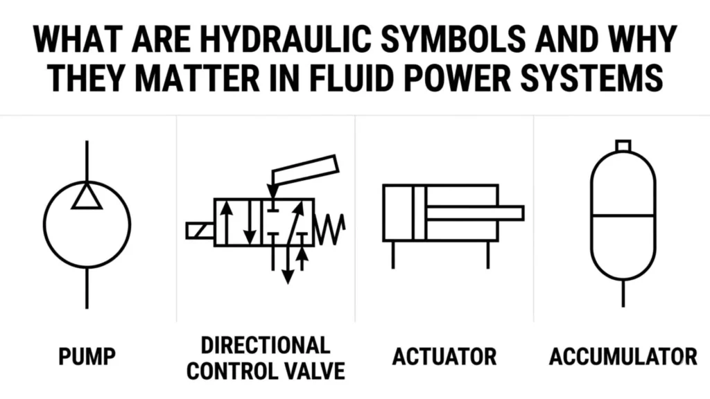
Hydraulic symbols are standardized graphical representations used to show components in a hydraulic system. Instead of drawing real machines, engineers use symbols to represent pumps, valves, cylinders, motors, and flow lines.
These symbols help in creating hydraulic circuit diagrams that are easy to read and universally understood across industries.
The main purpose of hydraulic symbols is communication. Imagine engineers from different countries working on the same machine. Without symbols, language barriers would create confusion. With standardized hydraulic symbols, everyone reads the same diagram the same way.
Why hydraulic symbols are important:
- They simplify complex hydraulic systems
- They reduce design errors
- They improve communication between engineers
- They help technicians troubleshoot machines faster
- They form the foundation of fluid power engineering
On an emotional level, hydraulic symbols represent control, precision, and trust. They give structure to powerful forces like pressure and flow, turning chaos into order.
History and Standards of Hydraulic Symbols (ISO 1219 and Engineering Evolution)
The system of hydraulic symbols did not appear overnight. It evolved as hydraulic engineering became more advanced during the industrial revolution and later in modern automation industries.
Early hydraulic diagrams were inconsistent. Each manufacturer used their own drawings, which caused confusion and maintenance issues. This led to the development of standardized systems.
Today, the most widely used standard is ISO 1219, which defines graphical symbols for hydraulic and pneumatic systems. This standard ensures that a valve symbol in Germany means the same thing in Japan or the United States.
Key milestones in hydraulic symbol development:
- Early industrial era: non standardized sketches
- Mid 20th century: rise of fluid power engineering
- ISO standardization: global unification of symbols
- Modern era: digital hydraulic simulation tools
Psychological meaning of standardization:
Standard hydraulic symbols reflect human desire for order. They show how engineers bring structure to invisible forces like pressure and flow. It is about control over energy that cannot be seen, only understood.
Did you know?
Hydraulic symbols are also used in simulation software where engineers test systems before building them physically. This saves millions in industrial design costs.
Basic Hydraulic Symbols Every Beginner Must Know
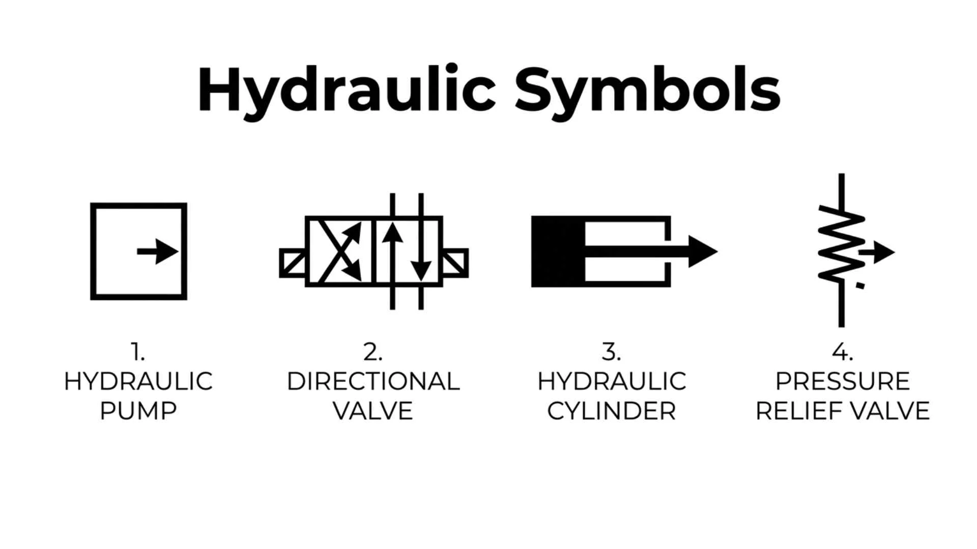
Before reading complex diagrams, you need to understand the basic hydraulic symbols. These are the building blocks of every hydraulic system.
1. Pump symbol
A pump symbol represents a device that converts mechanical energy into hydraulic energy. It pushes fluid through the system.
Emotionally, it represents creation of energy and movement.
2. Reservoir symbol
This symbol shows where hydraulic fluid is stored. It is the source of supply.
It represents stability and balance in the system.
3. Hydraulic cylinder symbol
This shows linear motion devices. It converts fluid pressure into straight movement.
It symbolizes force, strength, and direction.
4. Flow lines
These lines show the movement of hydraulic fluid. Arrows indicate direction.
They represent life flow within the system.
5. Filters
Filters remove impurities from fluid.
They symbolize protection and system health.
Understanding these basic hydraulic symbols is like learning letters before reading words. Once you know them, everything becomes easier.
Directional Control Valve Symbols Explained in Simple Language
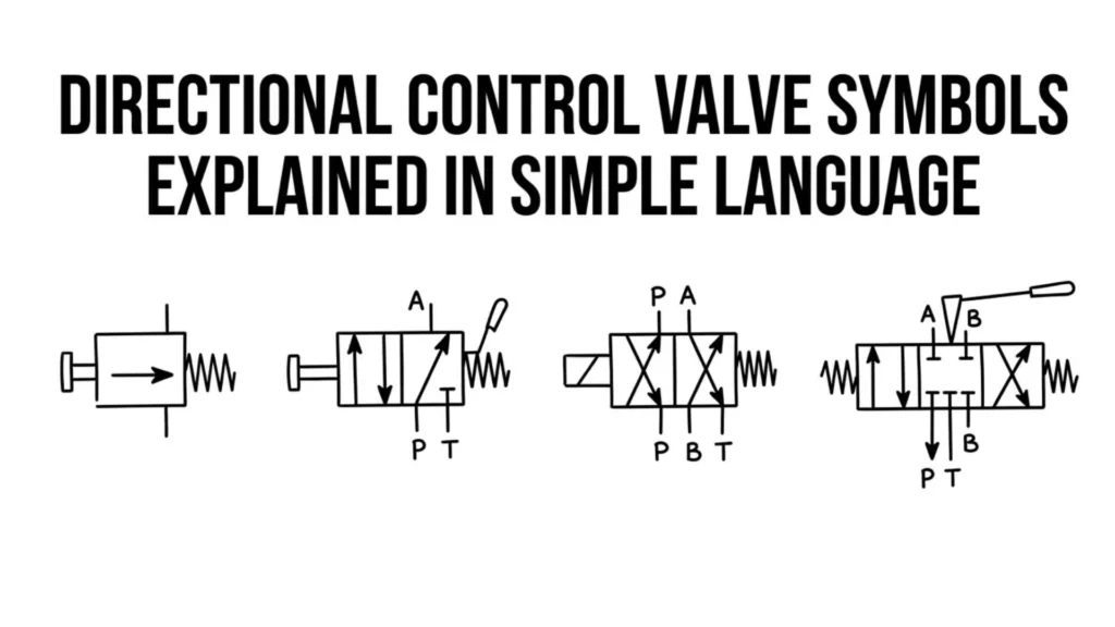
Directional control valves are one of the most important parts in hydraulic systems. Their symbols are also among the most detailed.
These valves control where fluid goes, when it flows, and how long it stays in a section of the system.
Common directional valve types:
2 way valve
Controls simple on and off flow.
3 way valve
Directs flow between different paths.
4 way valve
Used in complex systems like hydraulic cylinders.
Meaning of valve symbols:
Each box in a valve symbol represents a position. Arrows inside boxes show fluid direction. Lines show ports.
Emotional interpretation:
Directional control valves symbolize decision making. Just like choices in life, they decide where energy flows and where it stops.
Real world example:
In excavators, valve symbols represent how the operator controls arm movement, bucket rotation, and lifting power.
Hydraulic Pumps, Motors, and Actuators Symbols Meaning
Hydraulic systems are powered by energy conversion components. These include pumps, motors, and actuators.
Hydraulic pump symbols
They show energy input into the system. Pumps create flow and pressure.
They represent initiation and power generation.
Hydraulic motor symbols
Motors convert hydraulic energy into mechanical rotation.
They represent continuous motion and endurance.
Actuator symbols
Actuators create physical movement like pushing or pulling.
They represent action and physical response.
Psychological meaning:
These symbols reflect transformation. Energy changes form, just like ideas turning into actions in real life.
Industry relevance:
- Construction machines
- Manufacturing robotics
- Aerospace systems
- Agricultural machinery
Pressure Control, Flow Control, and Check Valve Symbols
Pressure and flow control are essential for safety and efficiency in hydraulic systems.
Pressure control valve symbols
These regulate system pressure to prevent overload.
They symbolize safety, balance, and protection.
Flow control valve symbols
These control the speed of hydraulic fluid.
They represent rhythm and control.
Check valve symbols
These allow flow in one direction only.
They symbolize discipline and restriction.
Emotional insight:
Check valves are like one way decisions in life. They ensure stability by preventing reverse movement.
Why they matter:
Without these hydraulic symbols and components, systems would become unstable and dangerous.
How to Read a Hydraulic Circuit Diagram Step by Step
Reading hydraulic diagrams becomes easy when you follow a structured approach.
Step 1: Identify power source
Start with the pump and reservoir.
Step 2: Follow flow lines
Trace how fluid moves through the system.
Step 3: Identify control valves
Look for directional and pressure control symbols.
Step 4: Find actuators
Locate cylinders or motors that perform work.
Step 5: Understand return flow
See how fluid returns to the reservoir.
Practical tip:
Always read from left to right or top to bottom depending on diagram layout.
Psychological insight:
Reading hydraulic diagrams is similar to storytelling. Every symbol is a character, and every line is a journey.
Did you know?
Engineers often annotate hydraulic schematics with color coding to reduce interpretation errors in large industrial projects.
Real World Applications of Hydraulic Symbols in Industry
Hydraulic symbols are not just theoretical. They are used in real machines that power global industries.
Construction industry
Excavators, cranes, and loaders rely on hydraulic systems for strength and movement.
Aviation industry
Aircraft landing gear and braking systems use hydraulic circuits.
Manufacturing industry
Hydraulic presses and robotic arms depend on fluid power systems.
Automotive industry
Brake systems and steering mechanisms use hydraulic principles.
Agriculture
Tractors and harvesters use hydraulic systems for lifting and control.
Emotional meaning across cultures:
- USA: innovation and industrial power
- Europe: precision engineering and safety
- Asia: efficiency and automation
- Africa: growing adoption in infrastructure development
Hydraulic symbols represent a universal engineering language that connects global industries.
FAQs About Hydraulic Symbols
1. What are hydraulic symbols used for?
Hydraulic symbols are used to represent components in hydraulic systems such as pumps, valves, and cylinders in schematic diagrams.
2. Why are hydraulic symbols standardized?
They are standardized to ensure engineers worldwide can understand hydraulic diagrams without confusion.
3. What is the most important hydraulic symbol?
Directional control valve symbols are among the most important because they control system flow.
4. Are hydraulic symbols the same everywhere?
Yes, most follow ISO 1219 standards, making them globally consistent.
5. How can beginners learn hydraulic symbols easily?
Start with basic symbols like pumps, cylinders, and flow lines, then gradually learn valves and control systems.
6. Where are hydraulic symbols used in real life?
They are used in construction machines, aircraft, industrial machinery, and automotive systems.
7. What is ISO 1219 in hydraulic systems?
ISO 1219 is an international standard that defines hydraulic and pneumatic symbol representation.
Conclusion
Hydraulic symbols are more than technical drawings. They are a universal language of engineering that connects ideas, machines, and industries across the world. Once you understand them, complex systems become simple and readable.
They represent control over power, structure within chaos, and clarity in complexity. From construction sites to aircraft systems, these symbols quietly keep the modern world running.
Learning hydraulic symbols is not just a technical skill. It is a way of seeing how energy flows through the machines that shape our lives.

Nicholas Allen is a passionate writer and symbolism researcher who explores the hidden meanings behind ancient signs, spiritual icons and cultural symbols from around the world. His work focuses on making complex symbolism easy to understand for modern readers.
He is the author of “Mystic Signs and Their Hidden Meanings”. Through his writing, Nicholas helps readers discover the stories, beliefs and mysteries connected to symbols across history and different cultures.